What is reaction calorimetry?

Calorimetry is a science that pursues the theory and measurements of heat released or absorbed by a system caused by chemical reactions, physical changes, phase transitions and such. Reaction calorimetry is a sub-type of calorimetry that specializes in measuring the energy released or absorbed during chemical reactions.
Simply put, reaction calorimetry is a discipline that enables chemists to perform thermal and kinetic analysis of their desired process in small scales (e.g. allowing for simulation of failure scenarios safely), and under realistic conditions (stirring, temperature, pressure, dosing ramps, etc.).
A brief history of calorimetry
The word calorimetry comes from the Latin “Calor” (heat) and “Métron” (measure).
Scottish physician and chemist, Joseph Black (1728-1799), is considered as the founder of the science of calorimetry, as he was first to recognize a difference between heat and temperature.
The first person to lay a solid foundation to calorimetry was Antoine Lavoisier (1743-1794), often deemed as the father of modern chemistry. He built the first device to measure heat exchange in 1782 with his colleague, Pierre-Simon Laplace. The device was designed to measure heat involved in various chemical changes (fig 1). The design was based on calculations and discoveries that Joseph Black published few years prior. The experiments performed with this device are considered as the foundation of thermochemistry.
The experiments with the device confirmed the Lavoisier and Laplace law of thermochemistry which laid the foundation to the modern understanding of energy and was fundamental for defining the First Law of Thermodynamics (the total energy of an isolated system is constant; it can be transformed into different forms but can be neither created nor destroyed).
How can reaction calorimetry help and where does it fit?
In past 40 years, reaction calorimetry has become an invaluable tool for process chemists and chemical engineers for determining reaction kinetics and optimizing known reactions (dosing profiles, process temperatures etc.), while the most important is the determination of process safety, especially when scaling up the production.
Generally, reaction calorimetry data should be available before moving the development of a chemical process to a larger scale (Kilo/Pilot plant scale). The data obtained will provide the heat flow profile of the reaction, on which the design of the larger scale experiment / production process should be built upon to run the process under safe conditions. With further testing, reaction calorimetry allows development of emergency protocols for failures during big scale manufacture, via simulation of the process on a smaller scale, which is easier and safer to control. This form of further testing can help industry avoid industrial disasters such as the T2 Laboratories explosion and fire where a lack of failure protocols resulted in a thermal runaway in the reactor.
However, this is not the only approach. Initially, the safety analysis was the main reason the technique was developed, but it can be applied in reverse order – chemists can scale-down existing processes and optimize them (for example when changing suppliers of chemicals), to attain greater efficiency in production. This technique is routinely used for semi-batch processes, however, it can be adapted to be used in pure batch or continuous flow processes.
In standard process development scenarios, the reaction calorimetry analyses take place during identifying synthetic routes, and afterward during optimization of the route selected. Reaction calorimetry will be usually accompanied by thermal screening (determining the thermal stability of the components/products), to establish most efficient and safe process.
Reaction calorimeters – how do they work?
It is possible to split reaction calorimeters into four groups, depending on the measurement technique used:
1. Heat flow calorimeters (HFC)
The first specialized reaction calorimeter was designed around the principle of heat flow, and it is still considered an industry standard to this day. The measurement vessel is essentially a jacketed reactor, and signals from temperature probes are used to calculate heat flux through the reactor wall, using the following equation (under steady-state conditions):
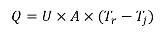
Where: Q is rate of heat transfer [W]; U is overall heat transfer coefficient [W (m2 K)-1]; A is heat transfer area [m2]; Tr is process temperature; Tj is reactor jacket temperature.
This technique has one major disadvantage. Since the U and A can change during the experiment, it is necessary to perform calibration to determine the UA before and after the experiment. When UA is known, the data is processed using the values obtained to correct it. The UA is determined by using a calibration heater of known power.
This means this method has limited use when UA changes considerably (change in viscosity, density, reactor fill volume). Those changes are often non-linear, and they are very challenging to correct (torque measurements etc.). Such corrections are normally sufficient for safety studies, however, heat flow calorimeters struggle when big changes of UA are observed. Because of the calibration pulses, the method can’t provide real-time data (as they are corrected afterward using the UA obtained from calibration).
The typical workflow of the Isothermal heat flow calorimeter is the following:
- Reach desired reaction temperature using circulator and reaching steady state conditions
- Perform pre-calibration pulse using a calibration heater to determine initial UA value
- Afterward, the reaction takes place with desired process conditions (additions etc.)
- Post-calibration pulse to determine final UA value
- Data processing, interpolating the UA values (done automatically), and calculating the specific enthalpy of the reaction (kJ), and calculating the scalable value (kJ mol-1).
With more advanced apparatus, HFC can be performed non-isothermally or under reflux with a specialized condenser, usually with lower accuracy and significant effort when interpreting the data.
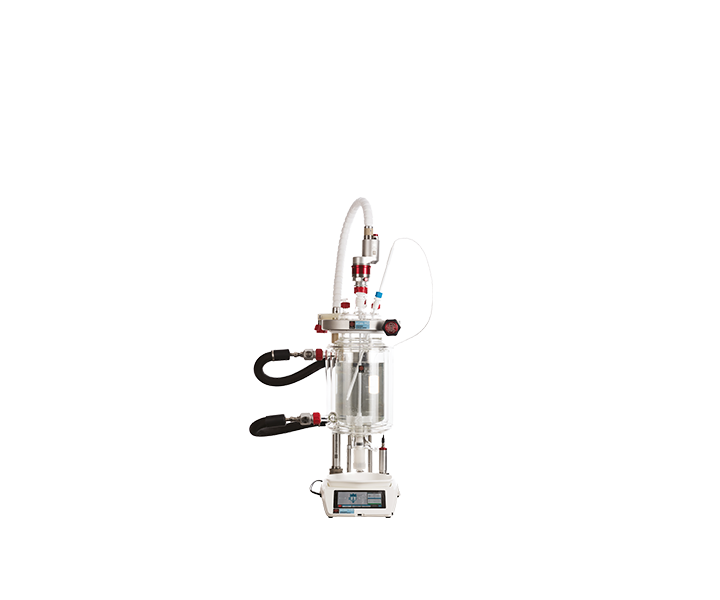
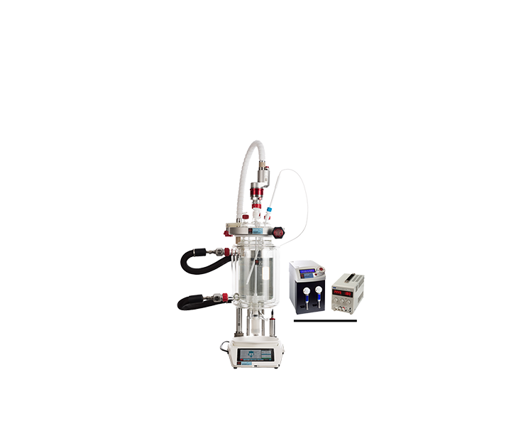
Isothermal heat flow calorimetry is the industry standard for safety studies and is one of the modes of operation offered by the Syrris Atlas HD Calorimeter. The results gained by isothermal heat flow calorimetry are considered accurate enough for most basic reaction calorimetry studies (e.g. monophasic reactions), but for applications where greater accuracy is required (e.g. studying explosives and propellants), its limitations mean a more accurate method is required (true heat flow calorimetry, explained below).
2. Power compensated calorimeters
Power compensated calorimetry (PCC) is the other widespread method of performing reaction calorimetry – it is a variation of heat flow calorimetry (HFC). The measurement of power is determined by the following simplified equation (under steady-state conditions):
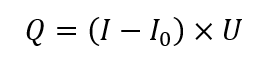
Where: Q is the rate of heat transfer [W]; I is the current supplied to heater [A]; I0 is the current supplied to the heater at steady conditions before experiment [A], U is the voltage supplied to the heater [V].
The system uses a cooling jacket with constant flow and temperature of the coolant, which is typically set 5 – 20 °C below desired process temperature. The process temperature is then maintained by the electrical heater with a large surface area. As the heat load of the reaction changes, the power of the heater is controlled to maintain isothermal conditions – so the inverse power supplied to the heater equals the heat generated / absorbed by the reacting system in the vessel.
The major advantage of this method is that it doesn’t require calibration, as the heater of known power is used to control the temperature of the reaction, shows real-time data, and typically, the system can achieve a faster thermal response, since electrical-based heating will respond faster than an oil-based system.
The major (experiment-dependent) disadvantage of power compensation calorimetry is the creation of hotspots created by the heater; these result in temperature gradients around the heater which can lead to local initiation of reactions. Power compensation calorimetry is also sensitive to changes in UA (as is heat flow calorimetry), and the maximum exotherm is limited by the available power of the heater.
Typical workflow of a power compensation calorimetry experiment (where the UA change is not considered):
- Heating: Reach the desired temperature with the heater (constant high power) and circulator on
- Settling: Once the desired temperature is reached, the heater remains on constant power and the circulator controls the temperature to reach steady state conditions
- Zeroing: Circulator temperature is fixed, and heater power is varied to keep the reactor at the desired temperature
- Reaction takes place with desired process conditions (additions etc.), while the exotherm is controlled by varying the power of the heater. The inverse value of the heater power shows actual reaction power
- Data processing
The UA changes mostly aren’t addressed with this method – if the experiment runs with significant UA change, it is possible to run in HFC mode – as most PCC instruments allow for running it without significant changes to the system.
Power compensation calorimetry is a method used for simple reactions (e.g. where the exotherm can be calculated before/or is known) and is one of the modes of operation offered by the Syrris Atlas HD Calorimeter.
3. Heat balance calorimetry
Heat balance calorimetry is slightly different, as it uses data obtained from jacket flow for calculation of the heat release / absorption. The difference between coolant temperature entering and leaving jacket is used to calculate heat exchange. The heat generated / absorbed by the system under steady-state conditions is as follows:
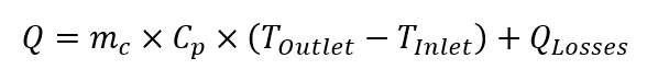
Where: : Q is rate of heat transfer [W]; mc is mass flow of the coolant [kg s-1]; Cp si specific heat capacity of the coolant at given temperature [J (kg K)-1] , Toutlet is outlet temperature of coolant [K], Tinlet is inlet temperature of coolant [K], Qlosses are thermal losses to the environment [W].
This method isn’t very often used in reaction calorimetry, but is very valuable in accessories, as this principle is used with reflux condensers used in reaction calorimetry, to calculate the cooling power of the condenser. However, it usually requires higher exotherms (to create the temperature gradient between jacket inlet/outlet) and is very sensitive to heat loss to the environment, which can be challenging to determine. However, compared to PCC and HFC it is not generally affected by changes in UA.
4. True heat flow calorimetry
True heat flow principle can be considered as a 2nd generation reaction calorimetry principle, as it removes most of the shortcomings of the methods described above. The main difference between true heat flow calorimetry and other forms of reaction calorimetry is a different reactor vessel construction, that doesn’t use oil as means of temperature control.
The main difference in the reactor is that the temperature control is achieved by use of Peltier element, which controls the temperature in the reactor via its metal base. The metal base contains a heat flow transducer, and since it is the only and well-defined area where heat transfer between reactor contents and the environment is achieved, it is not very susceptible to changes in UA.
The heat measured using this principle follows this equation:
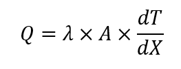
Where Q is the rate of heat transfer [W]; λ is the heat flow transducer heat conductivity [W (m K)-1]; A is heat flow transducer area [m2] and dT/dX is the measured temperature gradient over the transducer disk [K m-1].
From the equation, it is visible that none of the parameters are dependent on reactor contents, and don’t change during the experiment; this eliminates many shortcomings of the methods above and introduces advantages over them. For an additional level of precision, the whole reactor is placed inside in liquid bath with precise temperature control, which is kept at the same temperature as the reactor.
A major advantage of true heat flow calorimetry is that the reactor doesn’t require routine calibration; the reactor is calibrated during the manufacturing process.
A major benefit of true heat flow calorimetry for the user is that that the baseline doesn’t change over the course of the experiment (as with other methods due to changes in UA), so it’s not affected by changes in viscosity, fill volume, etc., and it delivers a higher level of accuracy and sensitivity.
A summary of the main types of reaction calorimetry techniques
| Reaction calorimetry principle | Advantages | Disadvantages |
| Heat Flow Calorimetry (HFC) | • Industry standard, well understood in the community • Can cope with large exotherms |
• Requires calibration pulses for UA determination • Not suitable for experiments with a considerable change of UA (viscosity, volume changes) • Long experiments • Slower thermal response |
| Power Compensation Calorimetry (PCC) | • Fast thermal response • No calibration needed |
• Not suitable for experiments with a considerable change of UA (viscosity, volume changes) • The possibility of thermal hotspots (local reaction initiation) • Maximum exotherm limited to heater power available |
| Heat Balance Calorimetry (HBC) | • Insensitive to changes in UA | • Usually the gradient between coolant in/out is very small, introducing large error margin |
| True Heat Flow Calorimetry (THF) | • No calibration needed • True heat flow measured in situ in real-time (what you see is what you get) • Insensitive to changes in UA • Excellent for large exotherms • Excellent sensitivity for low enthalpy processes • Ability to handle low volumes, multi-phase reactions, and non-isothermal modes • Due to lower volume of reagents needed, safer operation |
• N/A |
High performance Syrris Atlas Calorimeter aids process safety control at Pfizer
The versatile Atlas HD Calorimeter is proving a valuable asset to scientists involved in research and development at Pfizer, India, allowing them to perform vital process safety investigations.
We mainly use Heat Flow Calorimetry (HFC), but for some reactions, we prefer to use Power Compensation (PCC). We purchased the Atlas HD Calorimeter as it has the capability to perform both Heat Flow Calorimetry and Power Compensation Calorimetry, making it a really good addition to the laboratory.”